


TUTORIAL Editing .SMD 3D models (PS2)
Feb 26, 2022 13:34:30 GMT 10
Biohazard4X, christhehero07, and 2 more like this
Post by HardRain on Feb 26, 2022 13:34:30 GMT 10
Hey there, guys.
Today I'm gonna share with you something I have been trying to do since I started modding this game, edit SMD models on PS2 version.
At the moment of this thread, I don't have a way to import models from other games, but we can export and import any model from any room to another room.
I will split this thread into 3 parts for better following (it may be lenghty) and I will include a video guide which will be in portuguese, but with English Closed Captions [CC].
First of all we MUST understand the SMD file structure for quicker learning and modding steps.
The structure is quite simple, as shown in the pic below:

SMD HEADER
The very first line of any .SMD file will contain 3 important data: an index that represents how many objects entries there are in this room, a pointer to where the data for the pointers to models starts, another pointer that tells in which offset the textures starts.

ENTRIES
Entries are not to be confused with models. An entry in a SMD file is an instance of an object present in the model data. In simpler words, we use entries to make objects spawn, it is where we edit the Position, Rotation and Scale for the 3D models.
And in the last row of every entry is where we define which ID for the 3D model we want to spawn with this entry.
Example: let's say you want to spawn a chair, and the model is number 64, then you should simply insert 40 (64 in hex) at the entry ID byte.
There are also other bytes like SMX entry, which tells the SMD entry which SMX values will be applied to the model spawned, it is already documented here.
And the last relevant byte which tells the game if it will be a static object or a interactable/moving one, 8 = static, 9 = interactable (example: bridges we can raise).

POINTER FOR MODELS
With this title you can already undestand the meaning of this structure section. Here we find every pointer for every 3D model contained inside the room, they are in what we call "local scope", that means this section is separated from the previous data, so you can export the models easily this way.
Every pointer is made of 4 bytes and they are all in little endian. In case you do not know what a pointer is, basically it is a offset that points to where some data starts.

If we follow the examples here in this file, the first pointer points to offset 00 00 00 40, the second one at 00 00 0A 10, the third one at 00 00 16 C0 and it goes like that until all the models are pointed. Here we have 14 pointers for models, that means we have a total of 14 different 3D models inside the room.
If you notice well, the last two pointers are nulled 00 00 00 00, that means it does not point to any model, since there's no more models. And we can use these spare pointers too add our new 3D models.
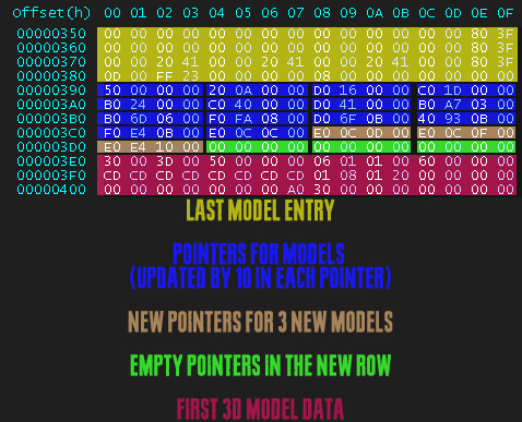
But let's say you want to add 3 new models and there's only 2 pointers available, in this case you should add a new row of 4 pointers and leave 00 00 00 00 at the ones you will not use; and if you add a new row of bytes, this will change the offset position for all the rest of the pointers, so you must update them all by 10, just like this:
MODELS
Right after the pointers is where the data for the 3D models starts, they are all .bin files very well organized in a sequential order. The index of each 3D model is their ID, that we should reference at the Entries to make them spawn at the room we're modding.
If you don't know the .bin file structure very well, I have made a deep research about it right over here, which I'd highly recommend you to see it at least to know where the Materials are located, just for better understading of the process.

In this model we have 1 material/texture, the second byte of the material row tells us which textures this model will use, in this case the third texture, since it starts counting at 00. All the textures are located at the end of the SMD file.
PADDING
This comes right after the last model data, it is a single row that ALWAYS starts with 10 and it is followed by many zeroes. The offset of this padding should be the inserted in the second pointer of the first row of the SMD file, as explained in the header section, because it activates all the textures for the models.

TEXTURES
One row below is where the data for the textures begins, there is a very well documented thread about .tpl files over here if you want to learn more.
Today I'm gonna share with you something I have been trying to do since I started modding this game, edit SMD models on PS2 version.
At the moment of this thread, I don't have a way to import models from other games, but we can export and import any model from any room to another room.
I will split this thread into 3 parts for better following (it may be lenghty) and I will include a video guide which will be in portuguese, but with English Closed Captions [CC].
First of all we MUST understand the SMD file structure for quicker learning and modding steps.
The structure is quite simple, as shown in the pic below:
Explaining the Details
SMD HEADER
The very first line of any .SMD file will contain 3 important data: an index that represents how many objects entries there are in this room, a pointer to where the data for the pointers to models starts, another pointer that tells in which offset the textures starts.
ENTRIES
Entries are not to be confused with models. An entry in a SMD file is an instance of an object present in the model data. In simpler words, we use entries to make objects spawn, it is where we edit the Position, Rotation and Scale for the 3D models.
And in the last row of every entry is where we define which ID for the 3D model we want to spawn with this entry.
Example: let's say you want to spawn a chair, and the model is number 64, then you should simply insert 40 (64 in hex) at the entry ID byte.
There are also other bytes like SMX entry, which tells the SMD entry which SMX values will be applied to the model spawned, it is already documented here.
And the last relevant byte which tells the game if it will be a static object or a interactable/moving one, 8 = static, 9 = interactable (example: bridges we can raise).
POINTER FOR MODELS
With this title you can already undestand the meaning of this structure section. Here we find every pointer for every 3D model contained inside the room, they are in what we call "local scope", that means this section is separated from the previous data, so you can export the models easily this way.
Every pointer is made of 4 bytes and they are all in little endian. In case you do not know what a pointer is, basically it is a offset that points to where some data starts.
If we follow the examples here in this file, the first pointer points to offset 00 00 00 40, the second one at 00 00 0A 10, the third one at 00 00 16 C0 and it goes like that until all the models are pointed. Here we have 14 pointers for models, that means we have a total of 14 different 3D models inside the room.
If you notice well, the last two pointers are nulled 00 00 00 00, that means it does not point to any model, since there's no more models. And we can use these spare pointers too add our new 3D models.
But let's say you want to add 3 new models and there's only 2 pointers available, in this case you should add a new row of 4 pointers and leave 00 00 00 00 at the ones you will not use; and if you add a new row of bytes, this will change the offset position for all the rest of the pointers, so you must update them all by 10, just like this:
MODELS
Right after the pointers is where the data for the 3D models starts, they are all .bin files very well organized in a sequential order. The index of each 3D model is their ID, that we should reference at the Entries to make them spawn at the room we're modding.
If you don't know the .bin file structure very well, I have made a deep research about it right over here, which I'd highly recommend you to see it at least to know where the Materials are located, just for better understading of the process.
In this model we have 1 material/texture, the second byte of the material row tells us which textures this model will use, in this case the third texture, since it starts counting at 00. All the textures are located at the end of the SMD file.
PADDING
This comes right after the last model data, it is a single row that ALWAYS starts with 10 and it is followed by many zeroes. The offset of this padding should be the inserted in the second pointer of the first row of the SMD file, as explained in the header section, because it activates all the textures for the models.
TEXTURES
One row below is where the data for the textures begins, there is a very well documented thread about .tpl files over here if you want to learn more.

